A spatial filter is pretty simple, it is a focusing lens, with a short focal length (mine is 4mm), and a pin hole. You focus the laser beam down to a spot, and then put the pinhole right at the focal point, so the light goes through it.
How is actually works is Really Cool... From the correct point of view, a lens does a Fourier Transform. The pin hole then selects the low frequency components. The Fourier Transform is then reversed as the light spreads out from the pinhole, and since there are no high frequency components, all the junk is gone.
So, why would building a spatial filter deserve a web page, much less a Saga? The issue is the size of the various bits involved. My pin hole is 10 micrometers in diameter. And that 10 micrometer hole must be positioned around a focal point, accurate to only a few micrometers. Green light has a wavelength of about 1/2 a micrometer. These things are built at just above the scale of waves of light. (Cool eh? :-)
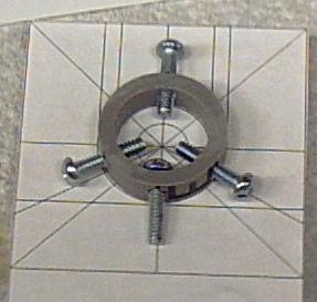
Anyway... My first attempt at building a spatial filter was a Plexiglas contraption. It used two of the finest screws I could get at Home Despot (I was shopping at the wrong place. I am reminded of that nearly every time I go to Home Despot...). Those screws were #4-40 thread per inch screws. They positioned a ring magnet which was stuck to a large washer, and held the pin hole. The magnet was held against the adjusting screws with a rubber band. The lens was a 40X microscope objective which sat in a V shaped groove, and was moved forward and backward with another 40 TPI screw. The pin hole was a hole poked in a piece of aluminum foil with a pin. (I read some pin hole camera web pages to find some tricks for making really small pinholes.)
While Attempt 1 mechanically worked, it was nowhere near accurate enough. The pin hole was also too big.
So I got a new pin hole (the 10 micrometer one), stuck it on Attempt 1, and tried again. The accuracy problem was too large, Attempt 1 was broken as designed. (But the exercise was not a waste, I learned a whole lot...)
So then I consulted a horde of web pages. Colin Kaminski's web page has some good diagrams. And started over.
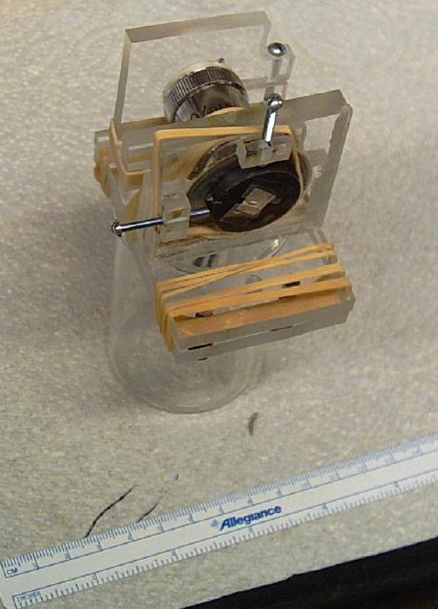
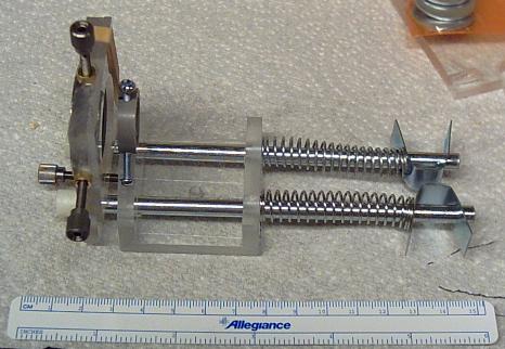
Attempt 2, like Attempt 1, and a lot of my projects, was made from Plexiglas. I drew up most of the details with Qcad, printed it out full size, glued the plans to the Plexiglas, and then just cut it out.
This time, I got some proper screws. I got a set of 127 thread per inch thumb screws from Thor Labs (where they are sold as 0.2 mm per thread). Optics is a bizzare mishmash of English and metric units... They don't make 127 TPI taps, so I also got some brass bushings. They specificly mentioned not to press-fit the bushings, the tolerances are too tight, and the bushings will deform. So I epoxied them. The bushings have an outer diameter of 5mm, a 13/64 drill bit is 5.1mm.
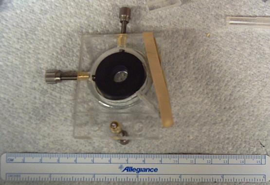
Attempt 2 used the same idea of a ring magnet sliding around on a washer for the x and y positioning of the pin hole as Attempt 1. A spring-loaded pin pushes the magnet against the two positioning screws. The pin is actually a #4-40 screw and a rubber band. It is also built the other way around from Attempt 1. The magnet and pin hole are on the "inside" of Attempt 2.
The lens I used in Attempt 2 was a 4mm lens from The Surplus Shed. They have lots of cheap optics, but the selection may not be sufficient if you want to get things like the correct anti-reflection coatings. Their optics are also pretty consistently dirty. However they are also 1/10 the price of new optics... So get some Q-tips and distilled water.
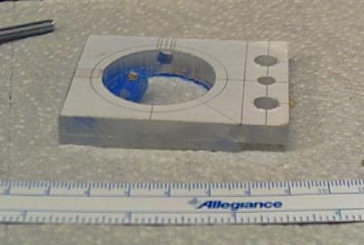
The lens is gripped by three screws. The ring the three clamp screws are in is then attached to the body of the spatial filter with a fourth screw. They are all #4-40 screws. The ring is a slice of PVC conduit which was sold to me as one inch conduit, but which is actually 7/8 inch outer diameter and 5/8 inch inner diameter. I needed 1/4 of an inch, and had to buy 10 feet, but it cost $1.09 anyway...
To adjust the distance between the pinhole and the lens, Attempt 1 moved the lens. To reduce alignment issues from moving an active optic like that, the usual procedure is to move the pin hole in the z axis. So, thats how Attempt 2 was designed.
The recommended part to fabricate rails to move the XY pin hole positioner is posts used to bind paper. I eventually managed to find some at an art supply place, where the magic word was "post extensions". Home Despot also had a few. Unfortunately, everyone's was too short. So I ended up using guide rods for bi-fold closet doors. It consisted of a smooth rod 1/4 inch in diameter and about 6 inches long, with a cap on one end and a spring and clip on the other.
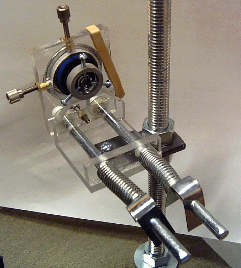
The body of the filter has a #8 screw sticking out the bottom. That screw is put through a hole in a steel bar, and held on with a wing nut. The steel bar in turn is held between two nuts on a vertical threaded rod, the base of the rod is mounted on whatever the optical table uses (weights, magnetic bases, etc...)